Lapey Street Motor Cart, 1949
Last Revised: October 22, 2023
French Creek Valley Home Blacksmithing
My Stuffed Metalworking Shop Storing My Stock
My Home Woodworking Shop Contact Us
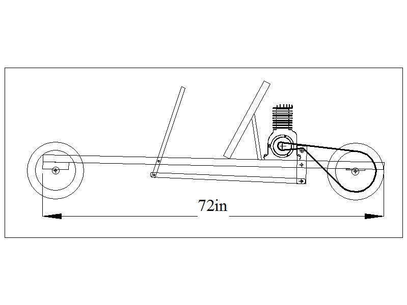
Side View of our Basic Motor Cart Design
Side View of our Basic Motor Cart Design
Basic Design Concept:
Our motor carts were about as simple as they could be. The main source of material was used "2-by" lumber from concrete
forming at construction sites. An 8 foot 2 X 10 or 2 X 12 and a 3 foot 2 X 6 were pretty much all that was needed.
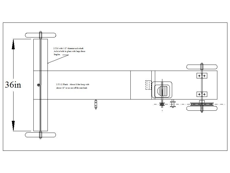
The finished cart was about 6 feet or so long. The front steering board was about 3 feet long, but the rear wheels were
placed as closely together as possible on either side of the 2 X 10 or 2 X 12 main "body". This gave the machine a sort
of reverse tricycle look. Since turning was accomplished by rotating the steering board with the feet and/or a rope,
this gave the machine a somewhat unstable posture at times. To minimize this problem, we avioded sharp turns at high
speeds.
The motors:
During the 1920's, 30's and 40's in the USA at least, washing machines in rural areas were powered by fractional
horsepower gasoline engines. Used ones were the primary source of our motive power. The single cylinder Maytag was just
barely capable of pulling us around. We used several different models of Briggs and Stratton engines, a Lauson or two
and, later on, one infamous Homelite. One of our guys did have a 2 cylinder Maytag.
Wheels and Axles and Drive System:
We usually used four 10" or 12" diameter wheels with 1.75 inch tires. These were called "semi-pneumatic" tires.
They had no inner tubes. They were simply circular hollow rubber tubes with tread, that were forced over a metal rim.
These wheels did have ball bearings. I think we always used wheels with 1/2" diameter bores. We had learned early on
that wheels with steel or brass bushings instead of ball bearings did not last long at the high speeds we subjected
them to, 8 to 12 miles per hour.
The axles were 1/2" diameter hot rolled shafting. I don't remember where the material came from. The front axle was held
in place with large fence-wire staples or simply with bent over nails. We hardly ever bought new nails. We learned how
to straighten used nails at an early age and there were plenty of them available at area constructions sites.
Early on, we mounted the rear axle the same way as the front axle. But the nails kept pulling out because of the forward
pressure from the belt tightener. So, we began to have two brackets welded to the axle shaft and to bolt the brackets to
body board.
Belts: I don't think any of us ever had a motor with a centrifugal clutch or with a chain drive. My dad came up with the
belt tightener idea that we used on almost all of our motor carts. Since the belt tightening system was also the
clutching system, there was quite a bit of wear on the drive belts. We needed even more slippage to get going than one
might espect for two other reasons:
-Most of our engines ran at a single speed, so there was no "start out at low rpms, engage clutch, increase rpms" in the
cards.
-Our engines didn't have much power, so we had to be careful to ease the engagement of the belt tightener for fear of
killing the engine. ---And some of them were pretty hard to restart.
Anyway, my dad was a centerless grinder foreman for the Burd Piston Ring Company back then. They used Besley centerless
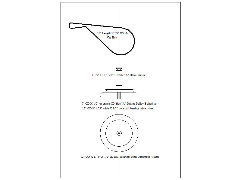
grinders for finishing piston rings. The spindles on these grinders were driven by a matched set of seven 51" long "B"
width vee belts. If more than 2 of those belts failed, then the remaining belts were scrapped. Dad brought these home.
So, all of the motor carts in our neighborhood used 51" B belts.
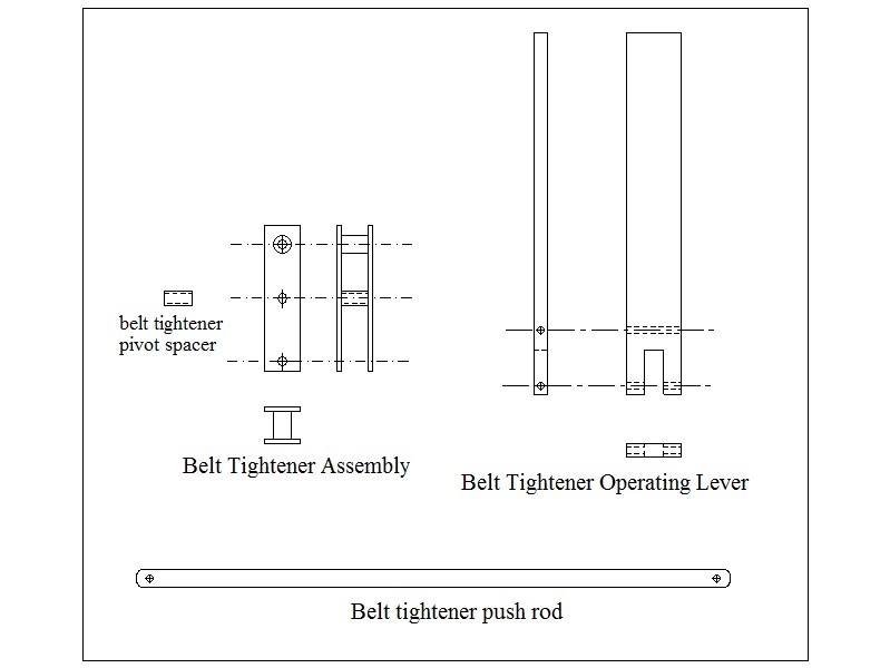
Belt tightening system: The belt tightener itself was made from two metal plates about 3/16 or 1/4 inch thick. 2" wide
and about 8" long. There was a centered pivot point, an upper belt tightener roller shaft and bearing and a lower
operating rod connection point. These holes were either 3/8" or 1/2" diameter. We had to have those holes drilled for us.
Fortunately for us, there was a junk yard/fab shop about 4 blocks from our house. Oscar Conquuist was the proprieter.
He was a major source for some of these services. He also had a box full of roller bearings, one size of which
worked well for our belt tightener roller. He also welded the mounting brackets to our back axles for us.
I think he charged 50 cents per visit, regardless of what we came for. The belt tightener operating lever
(clutch lever) was generally made from hardwood. When I was a kid, we still had many furniture factories on
our side of town, so there was a lot of 1 X 3 elm and oak around--- on weekends. We needed hard wood for this
lever because we were drilling through the 3 inch dimension and carving a pretty big notch out of one end for the
operating rod. The operating rod was always made from a piece of 1/2" EMT (electrical conduit).
We smashed the ends flat and drilled a hole in each flattened end for attachment.
Drive Ratio and Rear drive wheel: The best drive ratio was a 1 1/2" or 1 3/4" OD drive pulley on the engine with a 9" pulley on the single drive wheel. If we used 10" diameter rear wheels, the belt on a 9" pulley was almost touching the ground, but a 1 1/2" to 8" ratio made most of our motor carts very hard to get moving. Some motors had 5/8" diameter drive shafts, so if we couldn't find 1 1/2" or 1 3/4" drive pulleys we had to use a 2" diameter pulley in order to get a large enough bore. This, too, gave us start-up problems. It was not uncommon to see the operator pushing the cart with his feet while seated and while carefully engaging the belt tightener to get it moving. Attaching the driven pulley to the rear wheel was a big job for us. It required appropriately sized spacers and a good deal of accurate measuring to get the pulley firmly attached and well centered. This was one of the issues that took a lot of time to get right.
Additional notes:
A. Note that the pivot point of the steering board is off center to the front of the board. This makes for more positive
steering.
B.We used fence staples to attach the front axle, but later on we drilled at least one hole in the front axle so we could
nail it in place. This kept it from slipping sideways.
C.Setting the Seat-to-Steering Board distance: The actual driver needs to sit on the machine to determine this distance.
You want the driver's knees to be still slightly bent when the steering board is pushed all the way to one extreme.
If the driver's leg was totally straight, he/she could loose control of steering or be hurt. You also don't want the
driver's legs to be pulled up too tightly toward their chest when going straight ahead. This is uncomfortable on long
rides and also could contribute to a loss of control.
D. Repairs and refurbishing were a part of life with these carts. The tread life of the semi-pneumatic tires, especially
the drive tire, was fairly short. The pivot points (lag bolts) where the belt tightener assembly attached to the main
plank would wear from the stesses applied and wallow out the holes. We would insert slivers of wood into the hole to
refurbish it. Sometimes, we could reposition the offending pivot, but that usually caused other issues with fit-up of
mating parts. Belt replacement was also a regular duty, but as I mentioned previiously, we had an inexhaustable supply of
those 51 inch belts.
The main body board didn't even last for too long. A major problem was the leakage of oil from the engine, and sometimes,
gasoline from poorly made fuel line connections. The board would become so oil soaked that the belt tightener lag bolt
wouldn't stay tight. We could switch the whole main board front-for-rear once.
We also learned a lot about engines. We learned to solve problems with carburetion and ignition early on. Most of those
motors used a lot of oil. Maybe that's why guys from our generation are always checking the oil in our motorized stuff
today.
Closing thoughts:
it was not uncommon to get caught by someone and told that we could not drive our vehicles on the neighborhood roads.
None of the roads in our immediate neighborhood were paved, so it was a treat to go far enough away from home to find a
blacktopped road to drive on. It was on those roads that we usually got caught. Sometimes our own road/roads were so
bumpy that we would have to pull our motor carts for blocks just to find surfaces that were smooth enough for us.
There were no "weight challenged" kids in our neighborhood.
Points still to be integrated:
Rockford Morning Star article from about 1948 or 1949
Nystrom's race track
Homelite Story
Should I actually build one of these to get some pictures?