Little Giant-Mayer Bros. Power Hammer Identification Guide
Last updated: October 19, 2023
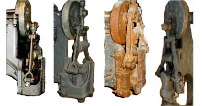
The "Actions" of 4 Styles of Hammers
This article should help you to sort out the differences between the basic styles of this popular brand of Trip Hammer (or Power Hammer as they are often called) in the 25# and 50# sizes. I have kept the picture size fairly small on this page so you can compare the machines all at a glance, and so they don't take forever to load. The figure numbers in this article all relate to the collage above. But you can click the links in this article to see a much higher resolution (larger) version.
Identifying the modelsMayer Brothers made many different styles of hammers beyond those detailed here, but these pictures, I think, cover most of the major styles.
When the Mayer Brothers were located in Mankato, Minnesota, they made 3 general styles of upright hammers as time marched onward,
the "old style", the "transition hammer" and the "new style". When a couple of the brothers moved to Kaukauna,
Wisconsin, they redesigned the hammer somewhat and these hammers are often referred to as "Wisconsin Hammers". Hammers from both
factories are discussed herein.
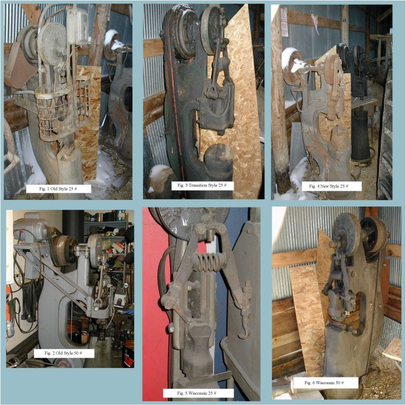
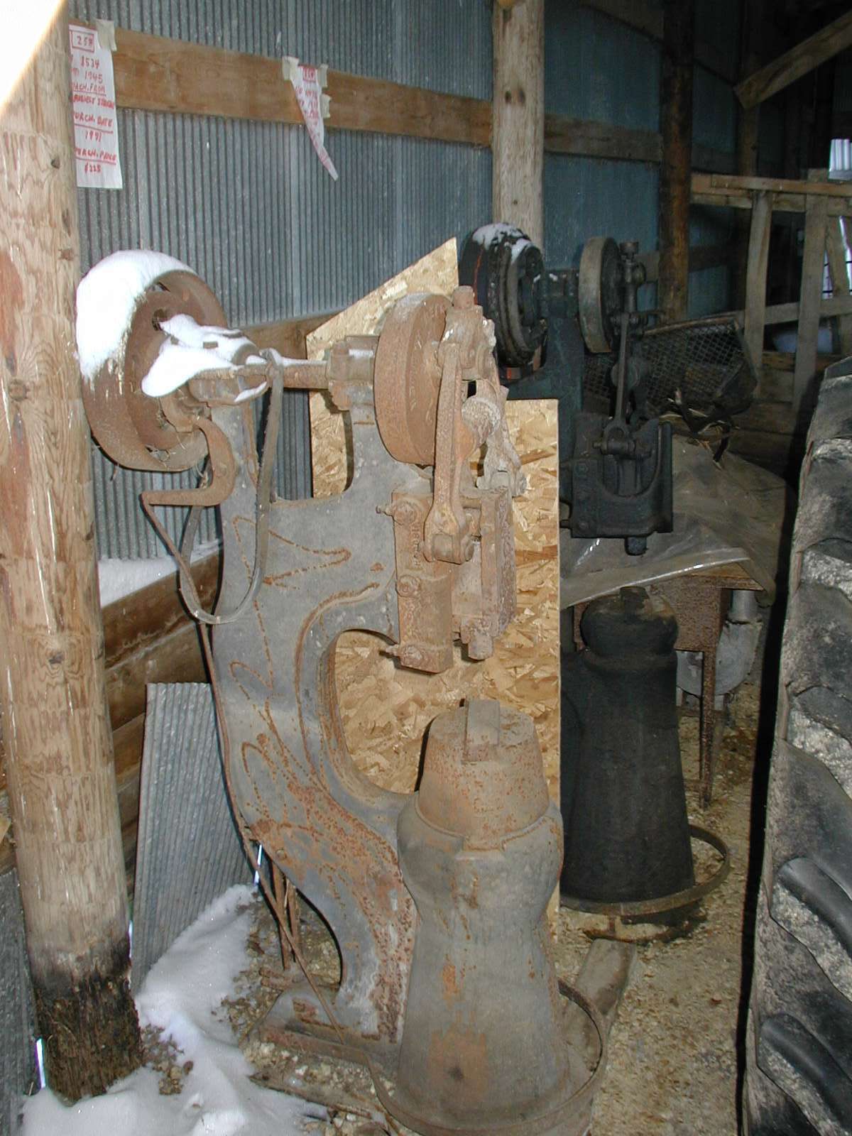
Figure #1 portrays the typical 25# Old Style hammer, but the example in the photo has a wireframe guard around the action,
so it is hard to see the "wrap around guide" that guides the hammer.
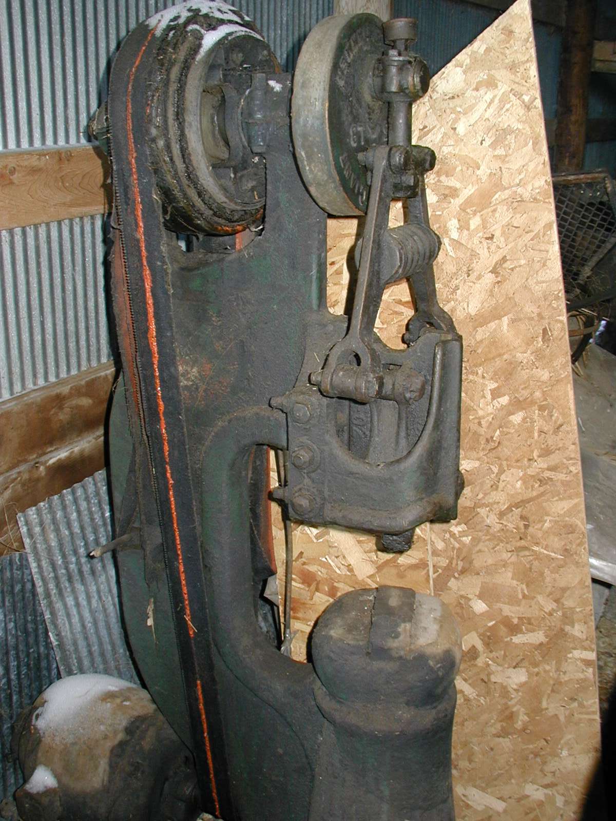
Figure #2 shows a 50# Old Style hammer and is a little easier to examine. In either case, you can see that the hammer (ram)
runs in front and rear ways. The rear way is machined into the frame casting and the front way is machined into the "wrap around guide".
The guide is attached to the main casting by 6 bolts running front-to-back. Adjustment of play between the ram and the guide is made by shimming the
junction between the guide flanges and the base casting.
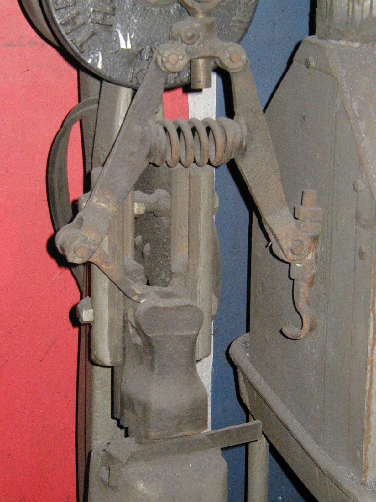
Figure #3 shows an example of the 25# Transition hammer. From the picture you can see that the guide still "wraps around" the ram (hammer), but in this case it is fastened with 3 thru-bolts going from left to right through the guide and the frame. Set screws are fixed to the back of the frame to allow for adjustment of "play" between the ram and the guide ways. The ways are still at the front and the back of the ram. This style was made only for a short time.
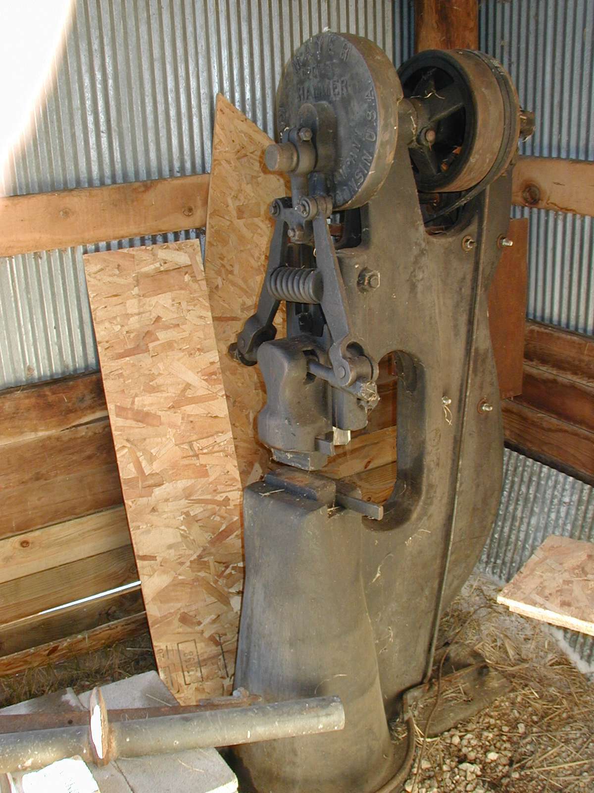
Figure #4 shows an example of the 25# New Style hammer. Here, the front guide is completely gone. The ways or "gibs" move to the sides of the hammer (ram). The ram sticks right out in front of the frame. The through-bolts are retained from the transition hammer to hold the gibs in place and to provide for adjustment.
Figures #5 and #6 show examples of the 25# and 50# "Wisconsin" (Kaukauna) manufactured
hammers. On these machines, the hammer is "out in front" like the "new style" hammers above, but the gibs are actually part of the
main frame. The frame is "sliced" vertically in the center behind the ram. This allows the through bolts to actually squeeze the gibs up
against the ram for adjustment of clearance.
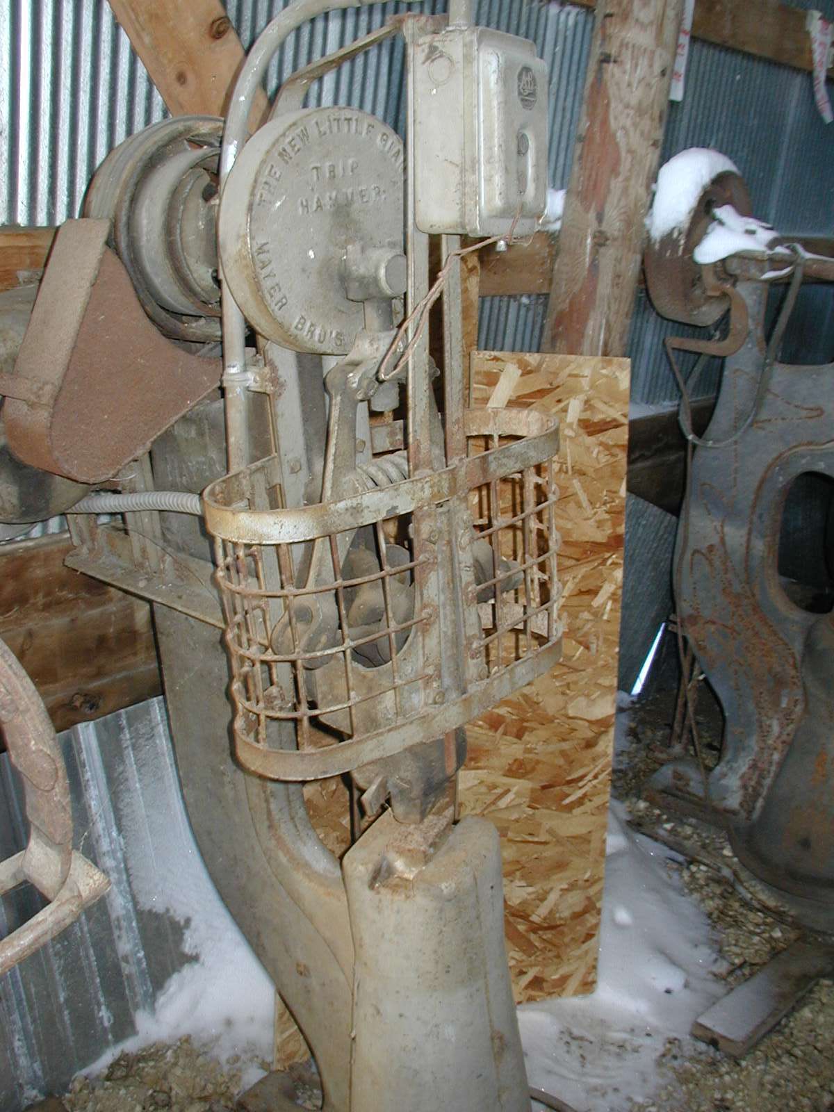
Another distinguishing feature of these hammers is that the bearing blocks are one-piece; that is to say, there are no separate bearing caps. The
drive shaft slides in from the front of the machine and is locked to the clutch spider by a tapered , threaded pin.
Lastly, in early 2015 a guy emailed me some pix of a Little Giant hammer design I hadn't seen before.
It has its own page at:
A Unique (to me) 50 Pound Little Giant Power Hammer Design from 1900
If you look closely at the pictures, you can see that on some of the examples the clutch pulley is in between the bearing blocks and sometimes it is sticking out the back. Some people say that the "inside" pulley is a sign of an older machine, but this is not necessarily true. The clutch pulley could be ordered either way. Between the bearing blocks, the machine was used on a line shaft and out the back was the setup for electric motor drive.
Some machines had removable sow blocks; some did not. I don't think they were available until the transition hammer came along, but I'm not positive.
Electric drive motors were mounted on the sides of the machines, down low, up high and, as you can see on the transition hammer, down at the bottom of the machine, centered, requiring a very long drive belt.
Probably 90 percent of all these hammers had flat belt pulleys. When used with electric motors, the motor speed must have usually been in the 840 to 1100 RPM range in order to keep the drive shaft speeds within stated ranges. A few of the late hammers had large diameter v-belt pulleys welded onto the flat pulley in recognition of the fact that electric motors in the 1725 RPM range were becoming more popular.
It is generally felt that the old style hammers hit a little bit harder than the new style. They certainly are easier to adjust.
All parts are still available for the Mankato-produced hammers, but very few parts can be had for the "Wisconsin" hammer. Phone Roger Rice (who recently took over from Sid Suedmeier at 402-873-6603 or email him at Lgiant@alltel.net for any parts needs.
Within the broad categories of "old", "transition" and "new", there were many other options that showed up from time to time. They even had one option where there was a hole about 3 or 4 inches in diameter right through the frame in back of the dies. I guess it would allow the operator to pass long parts right through the frame. I don't know why this was necessary since the dies are usually offset 15 or 20 degrees so that long work misses the frame anyway.
I won't apologize for the quality of the pictures, but it DID snow just before I took these shots and a little of it blew into the building
under the siding.
Hopefully you will now be able to "hold your own" at the chapter meeting coffee pot when these important matters are discussed.