Whatzit Vise Lathe?

First Posted: September 19, 2011
Solved: September 26, 2011
Last Revised: October 23, 2023


French Creek Valley Home                        Blacksmithing

1940's Motor Carts                        Contact Us

Here we have a "What is it" for you to ponder.
A friend brought it to the Guild of Metalsmiths annual conference. He got it at a garage sale. So far no one we know has any direct knowledge of its intended purpose.
Please contact me if you have any knowledge of this device.

If it were standing on end, one might think it's a post drill, except for the anvil component. 
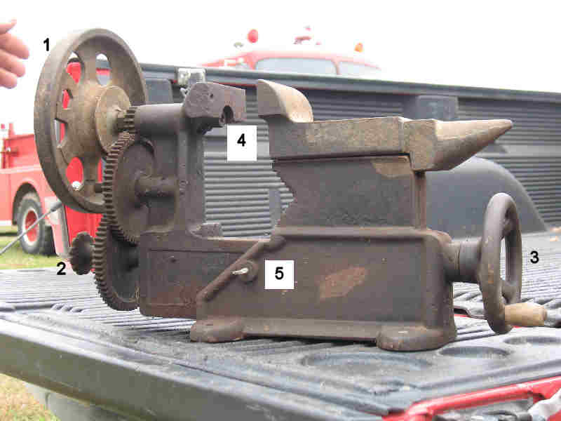
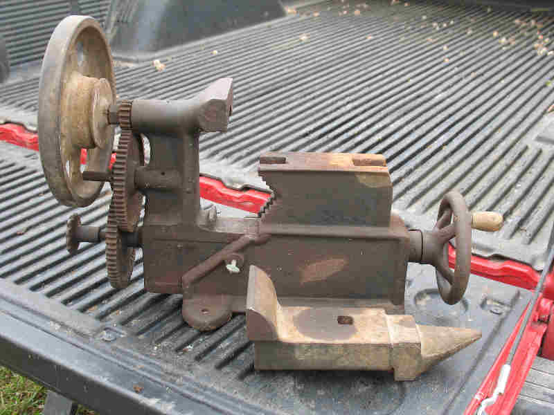
I have added a few callouts to the first of the three pictures to describe what we observed when we looked at it:
(1): This handwheel turns a shaft that goes through the "headstock" to item (4), which is a square socket of sorts.
This handweel appears to have been added at a later date, and we doubt that the vee pulley on it was ever used to drive the shaft.
(2):This wheel appears to have maybe operated a clutching mechanism that would have connected the gear train to the
(3) wheel at the other end of the machine. When we looked up into the bottom of the machine, all we could see were the
ends of the shafts. Rotating the (3) wheel opens and closes the "vise".
(5)This is a thumbscrew. There is a matching thumbscrew (broken off) on the opposite side. We guess their function was to lock the movable "jaw" , but we think they are pretty wimpy for that purposes.

Just to make things a little more confusing, notice the pipe jaws on the movable part only.
Vise Lathe or Horizontal Drill Tool
Vise Lathe 2
Vise Lathe 3

The Answers!

Okay, several people have offered ideas and a few have sent me references to similar machines. Curt Welch located the patent that best describes this version of "Convertible Machine Tool" invented by Theodore F. Timby. The following image shows the main view of US patent #836,657, which is describes a series of improvements to the original (I think) patent for his device. You can google the patent number to see all the text detail of how it all works.
Timby Convertible machine tool, spur gear spindle drive
Now here is an earlier patent for the machine, US Patent #701,424. This is the forerunner to the above patent. The nice thing about this image is that it shows many of the accessories that go with the machine. Note that this model used a chain drive for the spindle, instead of the later spur gears. It appears to me that the later model had more of a speed step up for the spindle, also.
Timby convertible machine tool, earlier version with chain drive
While neither of these patents exactly match the photos, I think we have gotten the answer to this one. I strongly suspect that field feedback and the search for manufacturing efficiencies and cost control contributed to the changes between the patent views and the pictures.